Contents:
Preparation
Checklist
Assuming
that you have all the necessary parts available and you are about to
solder them to the PCB, here is a checklist of things to do before starting:
- Make sure the Bootloader is programmed onto the PIC
microcontroller. You will need a PIC programmer hardware to do this.
See the general guide for
more information.
-
Download and install the firmware downloader software from
the Bootloader page. This program allows
you to download code (firmware) to the microcontroller. You will use it to
download the GoGo board firmware.
-
Download the GoGo board firmware from the download page. You
will eventually open this file with the firmware downloader previously
installed.
- Download the
Parts Map from the download page. You
can use it to figure out which component goes where on the PCB.
- Download and Install the GoGo board monitor software from the
download page. This program will be used to test the board from the
computer.
Recommended Assembly Sequence
Following this sequence allows you to test different parts of the board as you
build them. This makes it easier to debug when something goes wrong.
Please refer to the components map for a description of each part.
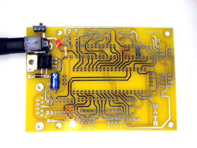
Step 1: Power Supply
|
Parts to Solder |
| 10 |
On/Off Switch |
| 3 |
Power Jack |
| 16 |
Power Regulator |
| 21 |
Diode |
| 4 |
On LED (Red) |
| 7 |
1K Resistor - next to the LED |
| 13 |
100 uF Capacitor |
|
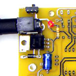
[Click to enlarge] |
After finishing this step, plug in the power adaptor and switch the
board on. The ON LED should light up.
Note: the numbers in the table refers to the numbers presented
in the component map document.
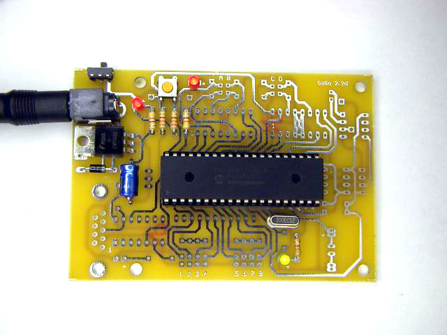
Step 2: Micro-controller
|
Parts to Solder |
| 1 |
40 Pin Socket |
| 15 |
RUN Button |
| 6 |
3.3K Resistors - under the button |
| 7 |
1K Resistor - next to the 3.3K |
| 4 |
RUN LED (Red) |
| 11 |
20 MHz Clock |
| 5 |
USER LED (Green) - under the clock |
| 7 |
1K Resistor - above the USER LED |
|
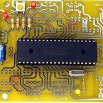
[Click to enlarge] |
When done, plug in the micro-controller. Then, hold the run button
while powering the board. Assuming that the micro-controller contains the
GoGo Bootloader (see checklist above), all three LEDs should light up
(Power, RUN, and User LEDs).
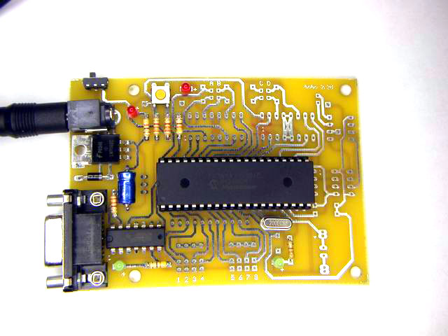
Step 3: Serial Port
|
Parts to Solder |
| 2 |
Serial Connector |
| 6 |
3.3K Resistor - next to the Serial port |
| 12 |
Hex Inverter Chip |
| 5 |
Serial LED (Green) |
| 7 |
1K Resistor - next to the serial LED |
|
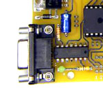
[Click to enlarge] |
When you are done, download the GoGo firmware to the board. Hold
the run button while powering the board. The same affect should happen as
before (the RUN, USER are on). Plug the serial cable to the board and to
the computer. On the computer, start the firmware downloader program.
Then, open the GoGo board firmware and press the download firmware button.
See the Bootloader page for detailed
instructions.
If the download process is successful it means the board is working
fine. If not, pleas check both the software settings (i.e. COM port
number) and the GoGo board hardware. You must fix the problem before
continuing.
Step 4: Complete the
remaining parts
| Notes for the Resistor Pack
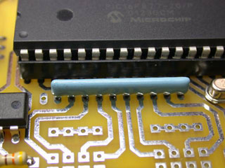
You need to be careful when assembling the resistor pack
(number 8). While the component has ten pins, the board contains
eleven holes. Leave the left most hole
empty. Also notice the polarity of the component. Pin
one (normally the side that has a mark or a dot) must be placed on
the right hand side. |
Step5: Final testing
Once you have soldered all the remaining components, start the GoGo
board monitor program on the computer. The monitor program allows you to
test all the functionalities of the board, such as sensor readings, motor
output controls, beep, user led.
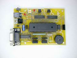
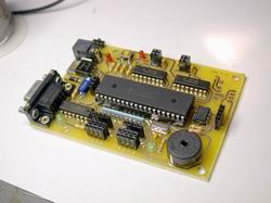
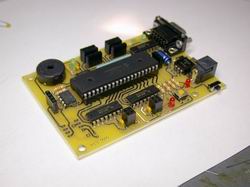
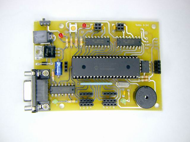
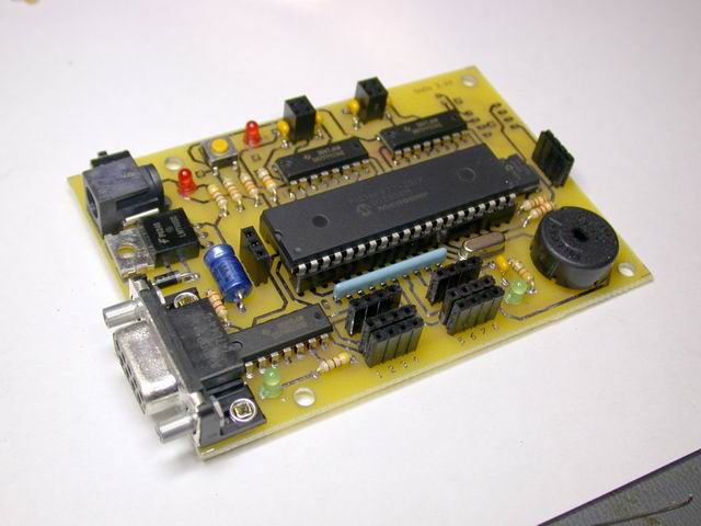
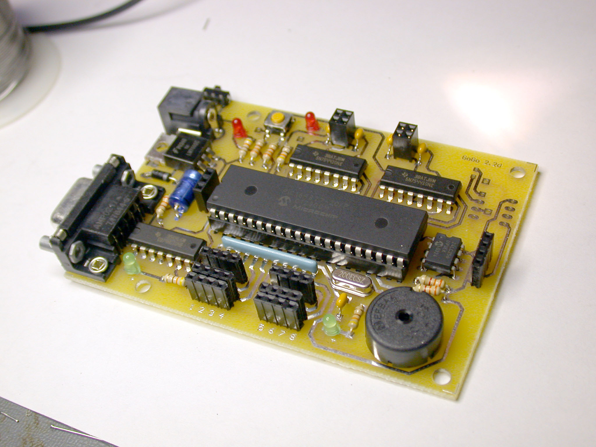
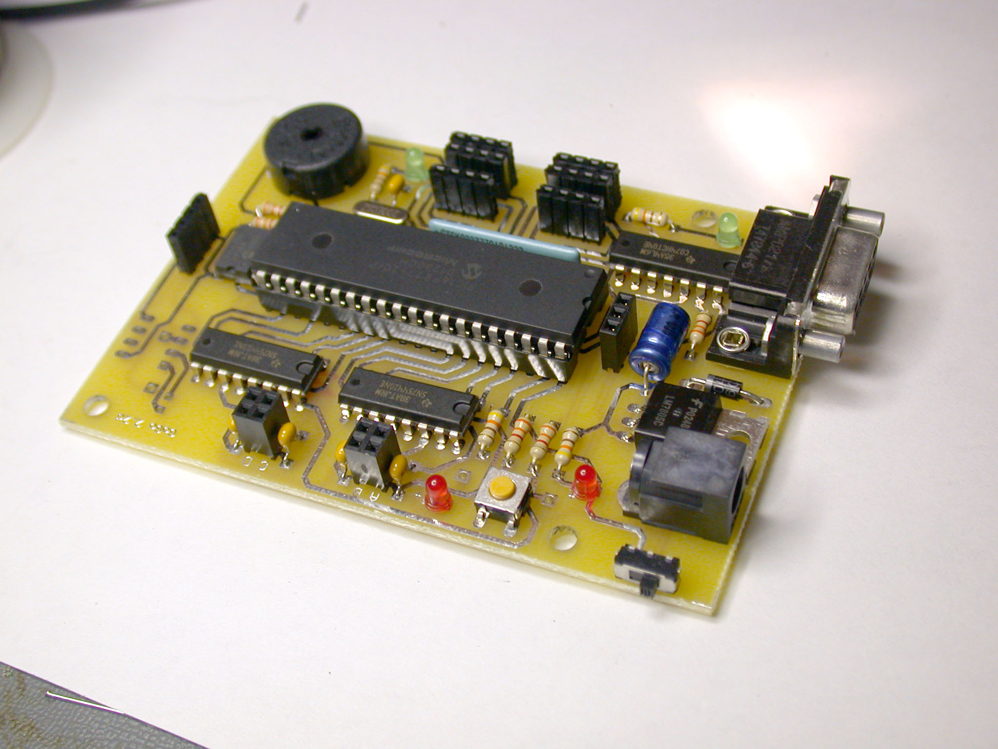
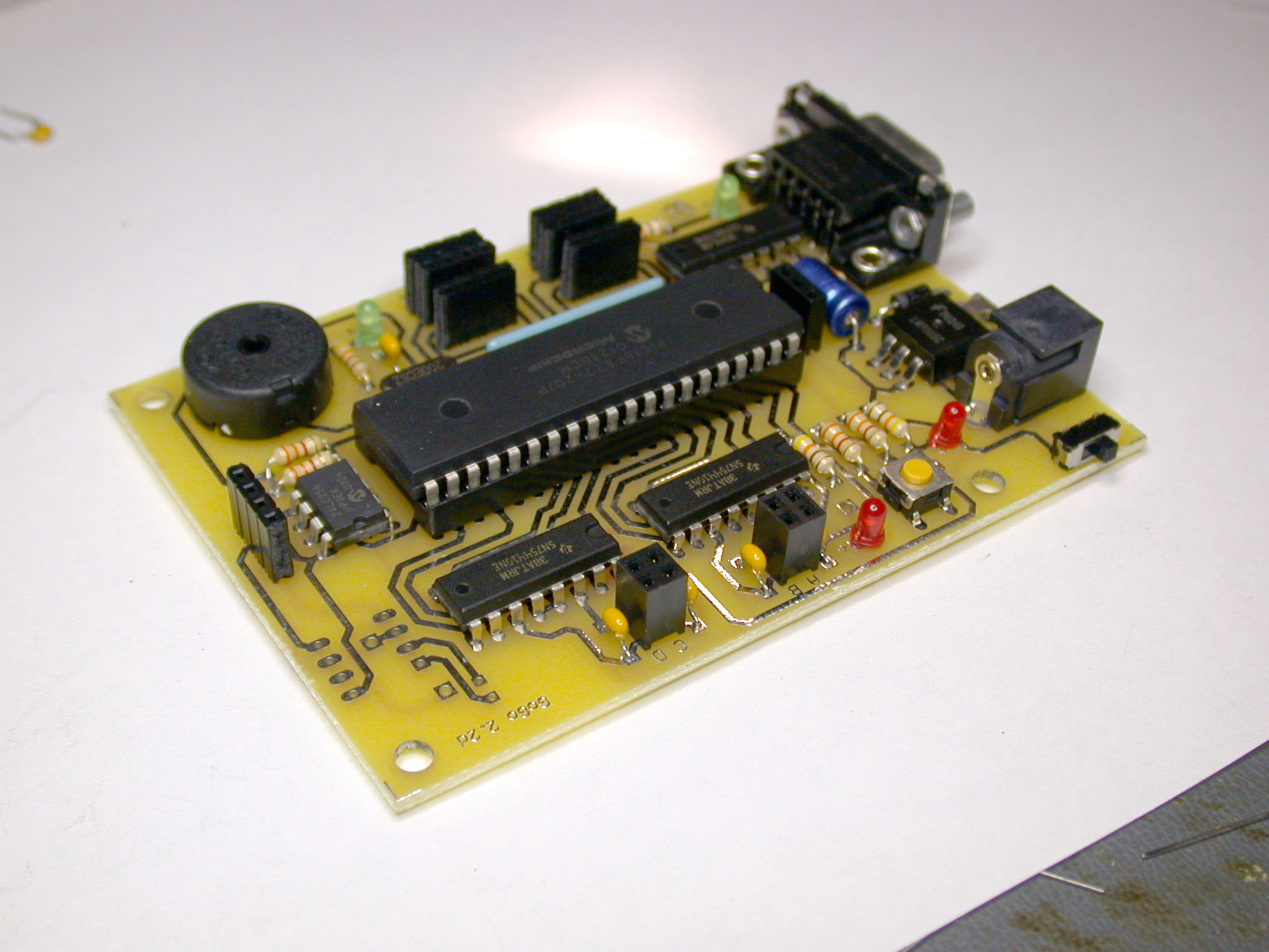
Photo Gallery
The following are some photos of a completed GoGo board.
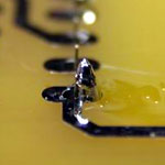
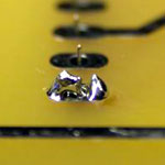
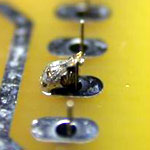
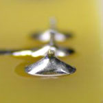
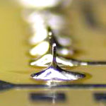
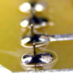
Good and Bad Soldering
Here is a guideline for when you solder components to a PCB:
- it is important to make sure there is enough solder between the
pin and the pad on the PCB.
- Sometimes having enough solder is not enough. You need to make
sure the solder is truly melted to both the component and the PCB.
This will happen only when both sides are sufficiently heated.
|


