|
Using
Motors
You can find motors everywhere, at electronic
stores, radio repair shops, or even in you old broken tape player. Most
of these motors can be used with the GoGo board.
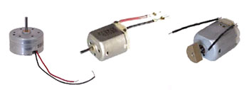
Different kinds of motors you can find
The important thing to know is the motor's rated
voltage. As I've mentioned in the previous section, it is best to match
this voltage with the output voltage from the GoGo board (9V). If you
buy motors, you should obviously ask for the 9V ones. But if
you have motor that is impossible to identify the voltage, there is no
reason not to try it. Here is what you should do:
Tinkering with Your
Found Motor Follow these steps if you
use a motor that needs less voltage than what the GoGo board gives (9V)
or if you don't know how much voltage your motor needs.
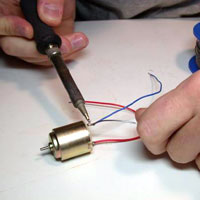 |
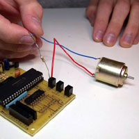
Solder leads to the motor
|
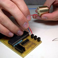 |
Connect the motor to the output
port on the GoGo board.
Turn on the motor
for a short
amount of time and see how the motor works.
Caution: Don't leave the motor on for too long,
as the motor could burn if its operating voltage is much lower than
what it is getting. |
| |
If the motor doesn't turn, that
means it requires more voltage than that the GoGo board can give. In
this case, I would suggest you find another motor (unless you want
to drive it with a
relay). |
 |
If the motor turns too fast,
that probably means we are giving it too much voltage.
In this case, run one of the wires through a
resister.
You should start with a resister value in
between 100-1000 Ohms. |
| |
Observe again, and reduce the
resistance until you are satisfied with what you see. The resistance
can go down to as low as 10 Ohms. Resisters can heat up. So, be
careful. |
|
Note: you can use a potentiometer (variable resister)
instead of the resister to speed up the process, as you can change
the resistance without having to physically replace the resister. |
Once you have determined the right resistance
value, you can solder everything properly.
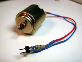
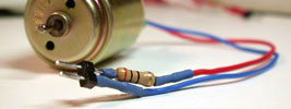
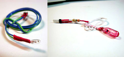
Example of a motor with a power limiting
resister
Bypass capacitors
When driving an inductive load such as motors, the
load sometimes generate noise back to the board. This noise can mess-up
the power of the board causing it to halt or reset. If this happens, you
need to add a small capacitor across the motor leads.
A typical bypass capacitor size is 0.1uF (0.1 Micro
Farad). Don't use polarized capacitors (i.e. ones that have one lead
longer than the other).
*Note that GoGo board 1.5 and higher has built-in bypass capacitors on
board.
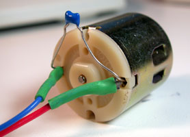
A motor with a bypass capacitor (blue).
Using Lamps
First of all, lamps in this case are much smaller
than the ones you see on the ceiling or in your desk lamp. If you want
to control those high power devices, you need to use
relays. Here we
are going to focus on small light bulbs and LEDs.
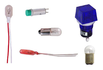
Lamp examples
Lamps
in the same way as motors, you should try to use
lamps that are rated at the same voltage as the output from the GoGo
board (9V). If they uses less voltage, you need resisters. Unlike
motors, lamps are more fragile than motors. So, you should never test a
lamp without a resister.
LED (Light Emitting Diode)
LEDs are similar to lamps but the light you
get is much more directional. LEDs also consumes less power. Thus, they
definitely need a resister to reduce the power from the GoGo board. You
should try something between 500-2000 Ohms.
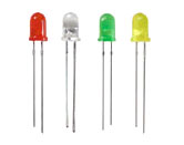
LEDs
Summary: thinker with you lamps and LEDs the same way you do
with motors, but NEVER try your lamps without a resister.
Using Relays Relays are very useful
when you want to turn on or off high power devices (i.e. desk lamps,
TVs, water pumps, etc). They are basically high-power switches that you
can control with the GoGo board.
The following diagram gives you a basic idea of
how a relay works. You connect the output from the GoGo board to point 1
and 2. This controls the magnetic switch that physically connects
point 3 and 4 together. It is point 3 and 4 to which you connect one of
the high power leads.
[A relay diagram]
Wiring a relay circuit
|
Caution: Let me first remind you that you are about to
work with very high voltage. Please make sure there are no bare
wires left anywhere on the circuit. Never allow children to work
with relays without a supervisor. |
Relays come in many shapes, but the most commonly
used relays comes in a rectangle box with five pins, as shown in the
figure below. [ image of a five pin relay -
map pin 1,2,3,4] Here are examples of other
layouts that are commonly found. [ image of
other kinds of relay - map pin 1,2,3,4] The
following diagram shows an example of a typical relay circuit.
[ Relay circuit] You
can use a simple extension cord for the high power wires. Cut one
of the wires and solder it to the relay. [
diagram showing how to cut the extension cord ]
It is a good idea to solder the relay and the
connections onto a perf board. Then you should screw the perf board onto
a piece of wood or plastic. This way, you can hide away all the
dangerous wires. [ illustration of relay,
perf board, wood base]
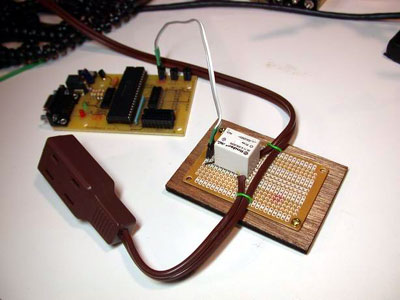
An example of a finished relay switch
module.
Testing the Relay
Plug the control wires (1,2) into an output port on
the GoGo board. Then, turn the port on (using any one of the software
libraries - see download page).
You should hear the relay "click." Turn it off and the relay should
click again. If this doesn't happen, check the connection and the solder
on the purf board.
Then, plug the high power wire into an outlet and
plug a lamp (or any other electrical device) to the outlet on the other
end of the wire. Now, turn the output port on once again. This should
turn on the lamp. [image illustrating the
test] |